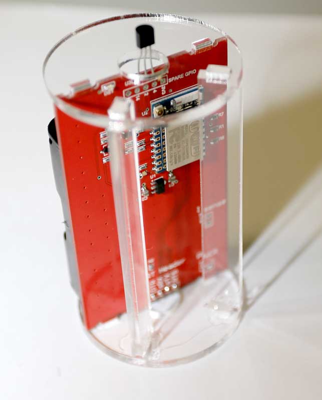
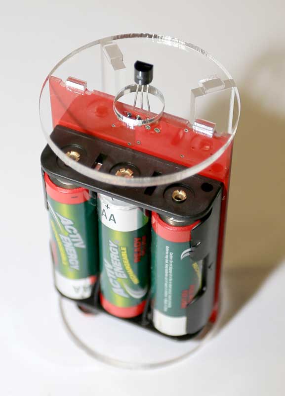
I finally got around to assembling and testing one of the boards I made to house a simple ESP8266, supporting stuff, batteries and sensor (DS18B20 in this case).
Not the most groundbreaking thing, but at least it’s no longer a bunch of wires between boards.
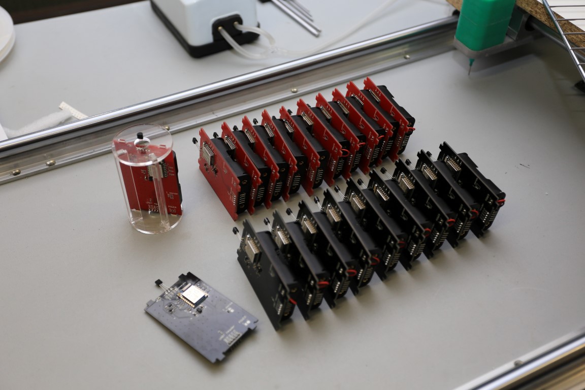
As I’ve said previously to folks at the space, I’ve got parts and boards for 20 of these.
If anyone would like to try their hand at simple-ish SMD soldering or would like it pre-assembled l’m happy to give them away to MHV members. You will need a USB to UART converter thing to program them, that was intentionally left off the board for simplicity and power reasons.
(Maybe surprising to some) It takes longer to kit them for assembly than it is to just assemble them. So if no one puts their hand up to build it themselves I’ll just run through assembling them in the next couple of days.
As I understood it, you implemented circuitry to isolate the adc pin, allowing measuring Vdd and battery voltage. Correct?
Or is there a mux to connect the two sources by request?
Currently the NodeMCU software required a reboot when switching between reading Vdd (when nothing else is attached to the adc pin) and reading an external voltage.
Just reading the battery voltage. The mosfet switch just allows you to disconnect the battery from the relatively low resistance voltage divider when you’re not measuring it.
There’s not a great deal of point measuring the Vdd voltage as it should be close to 3.3V or if the battery is going flat, close to the battery voltage minus 50 ~ 100mV.
This is my current piece of nodemcu test code for it (haven’t tried to optimise anything, but it works.)
-- analog battery voltage test

VDIV_EN_PIN = 6

ADC_CAL = 3.68/812.0

gpio.mode(VDIV_EN_PIN, gpio.OUTPUT)
gpio.write(VDIV_EN_PIN, gpio.HIGH)

tmr.create():alarm(1, tmr.ALARM_SINGLE, function()
  print("Battery Voltage: " .. string.format("%02.2f", adc.read(0) * ADC_CAL))
  gpio.write(VDIV_EN_PIN, gpio.LOW)
end)
I see. I am using gnd-1m-adc-10m-vbat divider so not worrying about the current there. You may remember me asking if those high values are too much for the internal ADC circuitry and the environmental electric noise.
I would think so. Sampling ADCs (like almost all uCs have) switch a cap across the input for a very short period of time before using the voltage stored across this cap to convert on. Therefore you capture a sample at an instant in time.
As a result of this sampling, the impedance across the input pin needs to be low enough to not be affected by the capacitance being switched across it. More complete ADCs have an opamp buffer on the input so they can be driven by high impedances, but it is uncommon on generic microcontroller ADC inputs. Some microcontrollers have an option of manually switching the sampling cap in software which negates this issue for slow changing signals, however I’ve seen no such function in the ESP.
Some microcontroller application notes I’ve read give a rule of thumb being a 10k input impedance or lower is required to maintain accuracy. So you’re away from that by two order of magnitude…
Yet another option is to put a cap in parallel with your 1M resistor to provide the switch current, but you need to check the cap’s leakage isn’t going to cause any significant non-linearities.
Basically I just took the belt and braces approach of switching in a low impedance. Probably costs an extra 10c in parts…
My aim to get it to a point where a reasonably technical lay person could get one that has been flashed, then set it up with thingspeak without dealing with any code.
I’ve written a web app hosted on the ESP that starts when power is applied. I’m using Bootstrap & JQuery so I think it looks quite reasonable. All configuration can be setup with that, then start the usual loop of posting data to the server and sleeping.
Whilst it took a bit of investigating to find all the pieces to put together, I’m quite impressed by what can be done with the ESP8266WebServer library. Makes building quite a complex API doable, and with gzip’ed js and css libraries one can store quite a bit on the ESP even with the 1MB flash.
All the functionality is there. Next stop is a code cleanup and refactoring, it’s a bit of a mess at the moment.
Well i have taken the boards to cooma with me, and i tried to set them up but, lo and behold the batteries that i have here are trashed … i know you just had some Aldi batteries in them , i tried some everyready gold (the shelf life may have come and gone) and also some rechargables as well with no luck booting the boards.
I get one flash of the blue and green leds and thats it .
I will get some fresher batteries today and see if i have any luck.
@crashman39, did you try to reverse the Rx/Tx connections? I find this a common issue when I use a different adapter of a different esp board. The one flash is what is expected. The connection speed should be 115200.
The other wires are not required when not flashing, so remove them and leave only GND, Rx, Tx connected.
well i thought that they would run with that firmware in them ?
btw Same thing happens when i have put new batteries in them but i will look at the firm ware and load it and see what happens
no this was just from the way we got them , i thought they may have been loaded with software , but from Derryn said there only the test software on them …so i will have a look in abit and report back
It boots into lua, so you should get a prompt (or reset the board by a quick short of reset (top left pin) to GND.
On bootup it prints some garbage first, then says it did not find init.lua, then gives the prompt (the details are with my fw):
NodeMCU 2.1.0 build dev-20170612-0944-512k-ow powered by Lua 5.1.4 on SDK 2.1.0(116b762)
lua: cannot open init.lua
>
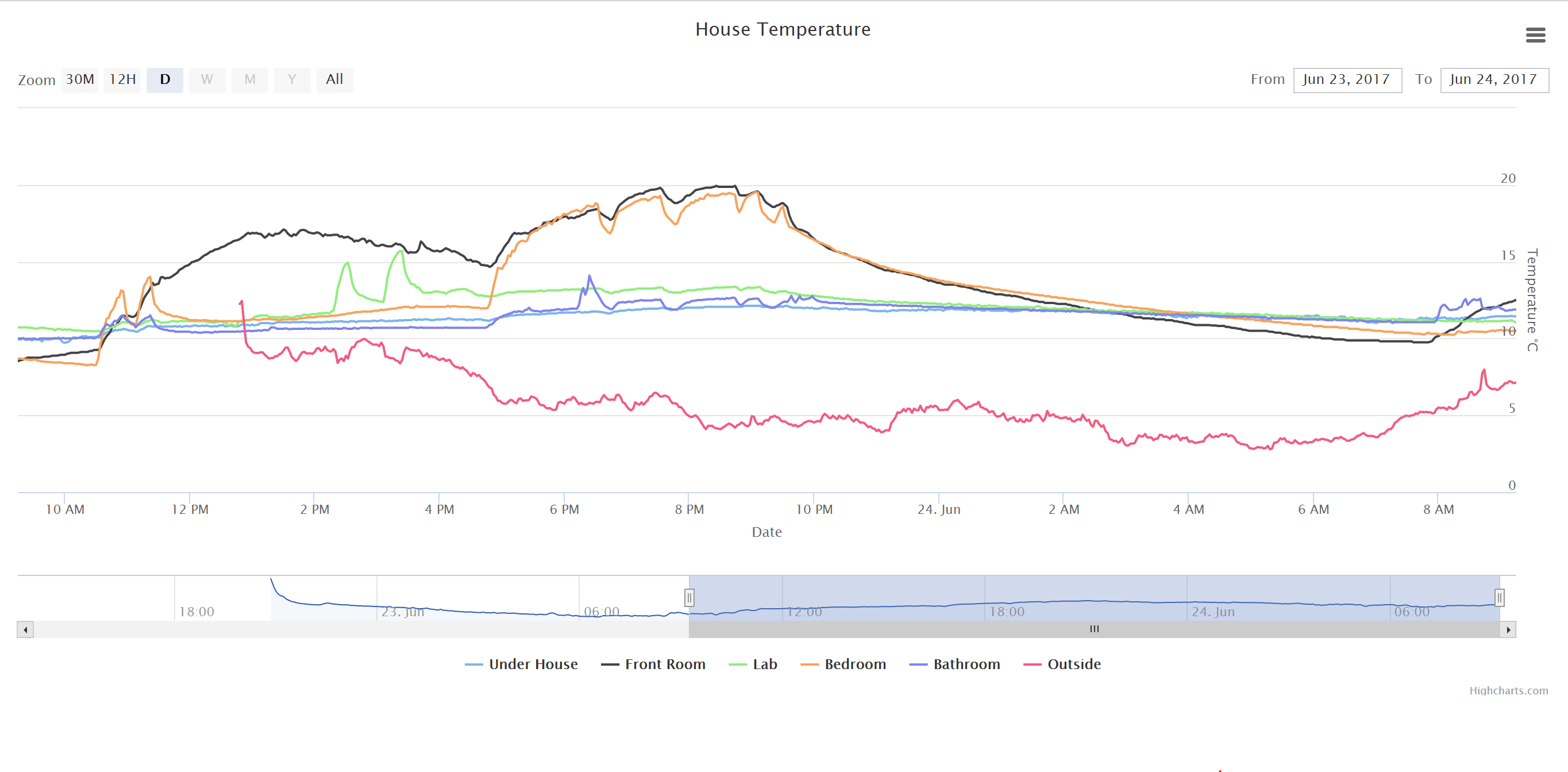
Some initial observations from using this board with my sensor app.
Using the full 1MB flash is not visibly slower than using only 512KB. A year ago when I tested this it was significantly slower. Maybe my measurement was at fault?
Flashing requires pulling down gpio0 manually. Connecting DTR (to DTR) and RTS (to CTS) does not activate flash mode. I now use only the three basic wires.
Not sure what the adc pin does but reading vdd does not give good result, so there must be some default load on this pin. I will teach my app to read battery voltage using the VDIV_EN_PIN pin as you describe. I thought that not activating the pin will leave the adc pin floating, as required for reading the vdd.
My app reports the reset reason, and here I get REASON_EXT_SYS_RST (6) when on all my other ESPs I get the correct REASON_DEEP_SLEEP_AWAKE (5).
I get weaker than expected signal. I have two boards, located very near the a/p (2-3 meters). My other ESPs connect with a reported rssi around -35 (or better) and these boards report around -50.
I haven’t tested this yet, but just copied that layout (using DTR and RTS) from someone else. It comes down to which software is being used to flash them, as control of the CTS/DTR pins is available directly from the controlling application. I believe it was setup for the esptool flasher, but I haven’t confirmed yet.
Nope, without the VDIV_EN_PIN pulled high, the ADC pin will be pulled to GND. If you wanted to hook it up to something else you’d need to pull a resistor or two off the board.
I’m interested in this as well, I have seen some inconsistent results with this (and don’t know why.)
I now read the battery voltage and getting a good reading. Board still uses 31uA in deep sleep.
I should explain why I want to read vdd too. My monitoring of the IOTs checks that vdd is good. Different boards use different batteries (3xAA, Li-Ion, LiFePO4, 5v from PoweBank) so monitoring these is difficult.
About wifi signal. Most of my boards use esp-12 of a few varieties, and as such have a printed antenna rather than a chip one. Maybe the printed antenna is more efficient? [later] I plugged in a pigtail antenna (left the on-board antenna in place) and the rssi improved from -50db to -33db.
Have looked into this a bit. Problem is you need the RTS line of the USB to UART, as that’s what they’re driving. CTS will never do anything, as it’s an input to the serial. I don’t currently have an adapter that has the RTS line broken out, might tack a wire on just to test.
esptool implements this and it looks like the Arduino IDE does as well (although there was a long thread of arguing whether to pull that functionality in or not as the Arduino serial monitor toggles DTR and RTS when opened.)
With the voltage divider you will always be able to monitor what you’re input voltage is, which would be fine for the first three (albeit you may need to change the top divider resistor to cover the full range of some batteries.)
For the 5V PowerBank, as we discussed the other night this is a bit more difficult since it already goes through a regulator. It’s likely internally the LiPo battery has a common ground with the output, so with a little bit of modification you could bring out the internal battery voltage and hook it up to the top of the voltage divider to give you an actual reading of the internal battery voltage. However that will negate the clean nature of just buying a powerbank and using the 5V output.
 .
.
 but i will look at the firm ware and load it and see what happens