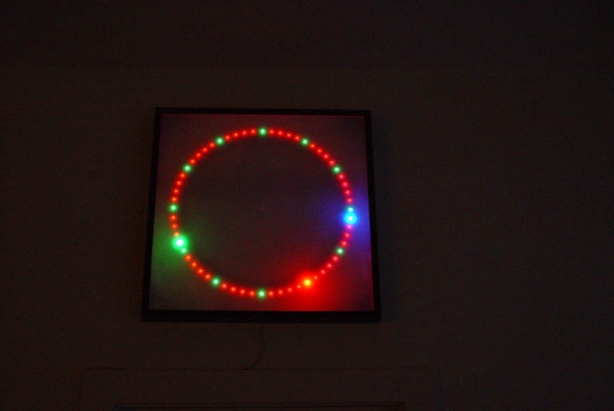
A cool piece of light art could be a clock made out of test tubes arranged in a circle to make an analog display. The hour markers and hands displaying the time would be created by illuminating test tubes.
Mock up displaying 12:22
Is anyone interested in this? It could hang at the space on the yellow wall.
I think that the best option would be to use led strip, soft plastic test tubes, and 3d print a frame.
Crunching some numbers the clock would need 3 metre of led strip, 180 test tubes, and end up ~1m in diameter.
I’m happy to design and make the frame which will align and hold the LED strip with the test tubes. I will make it from sections that join together.
I would like to share this project trying to make MHV a more interesting place and keen for others to take charge of things like power, control electronics, programming, etc.
@ian, can you elaborate on the design you have in mind? Why 180 tubes? I thought 1 RGB LED in a tube for each minute should do the trick? I see three bright LEDs is the image here - does it show a seconds hand?
Clearly I do not see what you aim for.
BTW, for people embedding links to AX, there is no need to copy the whole shebang (the long list of numbers at the end is just tracking the poster), all you need is the item code: https://www.aliexpress.com/item/-/2036819167.html
It is a mix of cost, aesthetics, maths, but mostly topology.
The count of elements in the clock needs to be a multiple of 60 and the tubes and the lights need to match.
Test tubes come in 12mm, 16mm, and other diameters. The longer the test tubes the better, but more expensive.
Plastic tubes:
75mm tubes $0.09US each
100mm tubes $0.10US each
150mm tubes $0.35US each
etc
Glass tubes are even more expensive. Disposable tubes are cheaper at $0.04US each, but only come in 100mm x 12mm.
The distance between the LEDS needs to be greater than the diameter of the test tubes, and then some; as the ends of the tubes pointing into the circle will be closer together than the opening near the LED strip.
The LED strip comes in 30, 60, 74, 100, etc counts / metre. But because the distance between light needs to exceed +12mm only 30 or 60 LEDS/metre will work.
So there are 2 workable permutations:
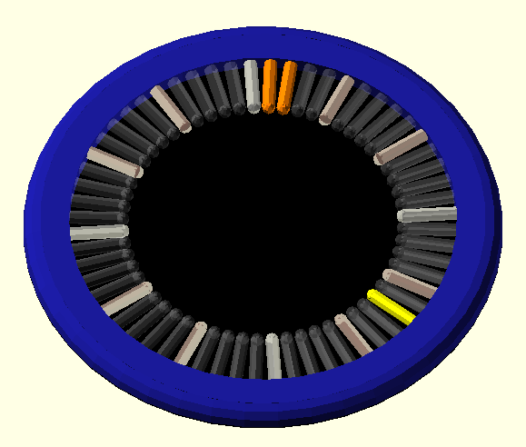
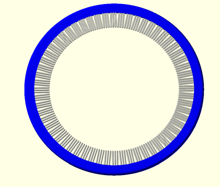
60 tubes either 100mm x 12mm, [or 150mm x 16mm if you want to pay x4 more]
2 metre of 30 LEDS / metre ws2812b strip
Cost ~$25us / $70us
Outer diameter 70cm,
and looks like:
Or
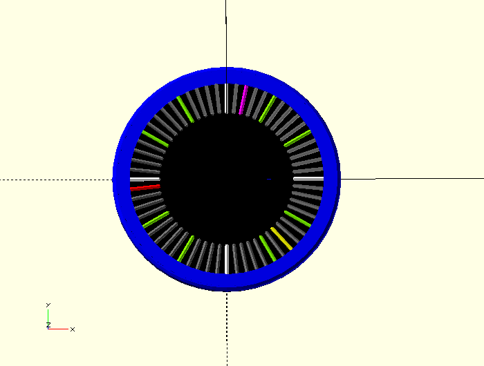
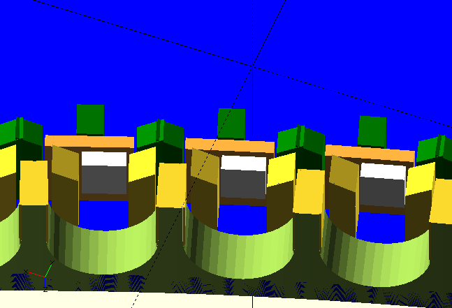
180 tubes 100mm x 12mm
3 metre of 60 LEDs / metre ws2812b strip
Cost ~$30us
Outer diameter 100cm,
[Will also have 3 time resolution for smoother animation]
and looks like:
Given your wish for people to get involved, to throw an option in, there are a few people who seem to never get around to learning to designing a PCB.
Instead of using the pre-made ws2812b strip someone could design a PCB segment that fits inside the 10x10cm standard square. It’s ridiculously cheap getting 2-layer PCBs made these days (like $2 for 10x + postage), then buy the LEDs and assemble.
I guess roughly a 1m diameter clock will have a perimeter of ~3.14m, a 10x10cm square has a diagonal of ~0.14m, so first approximation would be 23 boards to make the perimeter, so only maybe $10-15 worth of PCB + parts.
It would be a cheap and easy first board to design and assemble for someone wanting to have a go.
Also might open up some interesting lighting ideas (e.g. multi rows of LEDs of different types? Who knows…)
Well, we do NEED two clocks, one for each of the two rooms, right? We should try the two above approaches. And if anyone has other ideas (3D printed faceplate with LEDs inside coloured segments?) we can have a clockfest.
Anyway, I am game to participate, and PCB design is something I was trying to get into for a while.
BTW @Harvs, I expect the number of PCBs is not simply the clock circumference divided by the PCB diagonal. We need to fit 60 equidistant LEDs (or a multiple of). Assuming one PCB design.
Agreed, and you can integrate into the design some sort of solder together inter-locking shape to make assembling the whole thing easy (as long as the shape can be routed with a 1.6mm bit). The number I came up with was purely a rough order of magnitude to guess at cost. $15 + p&h should easily get you 30 boards. Of course you can get any multiple of 10 of any design for no additional cost, so they don’t all have to be the same design.
I don’t mind how it is done, if you want to get PCBs fabricated thats cool.
The plan for the frame so far has been to have a
‘U’ shape where the test tube will sit,
A slot to hold the LEDs and strip in the right position, and
~5cm of space round the edge for electronics / wires etc.
If using PCBs to change model I will need to know things like the size of the boards, how many leds each has, placement of the LEDs on the boards, where wires and other components are. Etc.
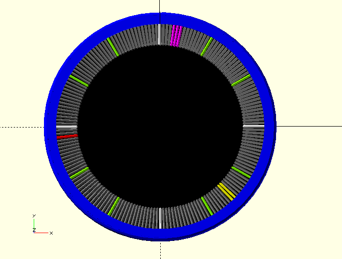
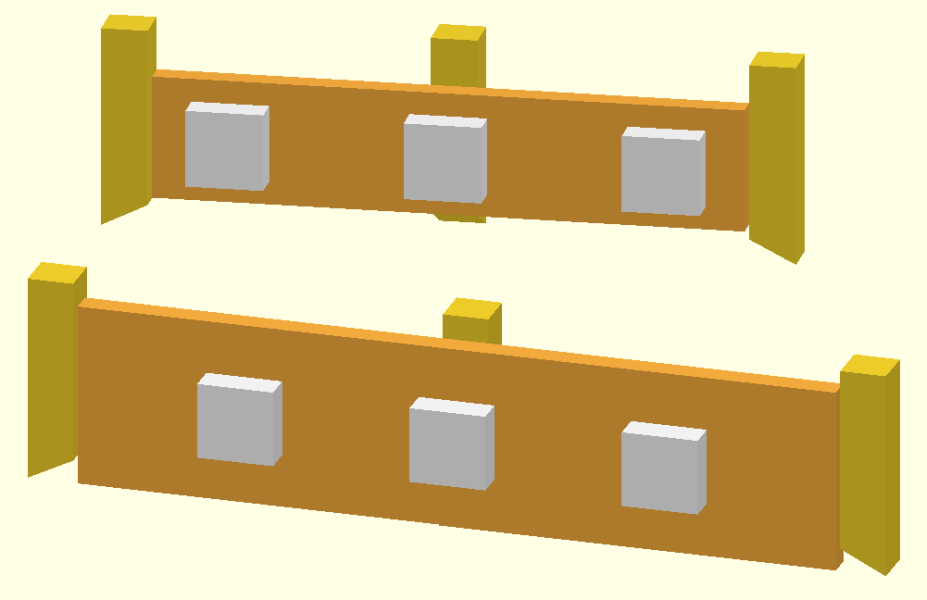
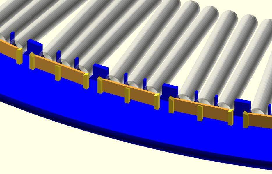
This is the current idea, that can change to PCBs instead.
Blue: outer frame,
Red: Structure for LED strip
Yellow: structure for test tubes
Black/White: Strip and LEDs,
To keep things moving I have mocked up a 3d frame model assuming the use of small PCBs - with one LED each. Note I am not perscribing that is how it should be done, just an arbitary choice. [Blue: outer frame, Greeny/yellow: Test tube clip, Brown: PCB, Green: PCB clip]
I can order the test tubes.
@eyal what are you planning to do? and what do you need to do so?
What is the process for getting some PCBs made if that is what you are doing?
And how big will they be?
Assuming we go for the cheap 10x10cm PCB, I expect that we can fit a few rectangular modules on each PCB.
Do we want a few (2? 3?) LEDs per module? or just one?
How many tubes (per minute) do we want? This will determine the size of the clock (as described earlier).
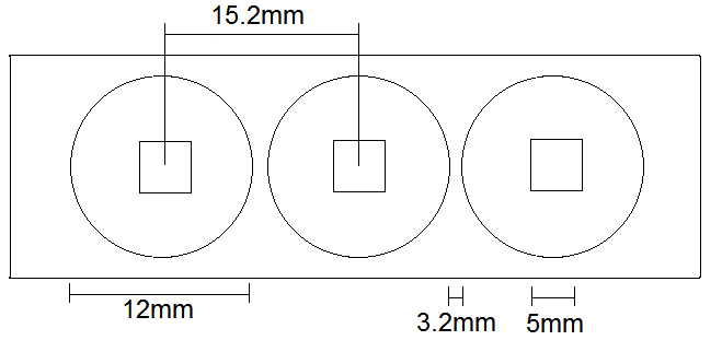
More ‘minutes’ per board will mean less wireing and the like, but 1 board per minute and ~3 LEDs per board would look nicer. The test tubes will require a minimum of 12mm + ~3mm printed frame each. if the LEDs can be arranged with say 15.5/16mm spacing and the whole board not extend too much before/after the first/last LEDs it should be workable.
I was hoping to make the frame height just larger than the diameter of the test tubes (12mm). It would be best if any connectors / wires could arranged in a way that doesn’t require more height. I.e. wires can come out the back or sides, but not the top or bottom.
Mounting boards to the frame options:
clips or slots printed into the frames - if the boards can be accurately cut to the right size,
small screws (say M3x10) - if holes can be positioned consistently and in a place that doesn’t affect the position of the test tubes, or
worst case hot glue.
Will the LEDs be SMD shining ‘up’ from the flat surface of the board, or will they be on the edge of the boards shining out the sides? (Or something else)?
I will make time to change the frame model and explore how many LEDs, PCBs, and test tubes, will fit on boards next to each other.
I don’t think I can make it to the space this week sorry.
I have changed the model to explore using PCBs with LEDs. It is workable, but I found it harder to come up with neat arrangements compared to LED strip which has fixed spacing, and is flexible.
The expectation is that the boards will be made on 10x10cm PCBs, so attempting to fit a few boards on each PCB will make it cheaper.
As for wiring, it can be mounted on the back of the boards so no spacing is required between them. We could even directly solder the boards? Connectors will allow easy replacement of failed boards.
Thinking about the dimensions. 3 tubes of 12mm diameter will be 36mm wide, the LEDs centers will be 24mm apart, so we could easily fit three along 100mm. How wide will each board be? It will depend on the number of connecting pins (at 0.1"=2.5mm spacing). I did not work with RGM LEDs so need to find this out.
I also wonder why three tubes per minute - what is the purpose here? Also, will the LEDs show a seconds hand?
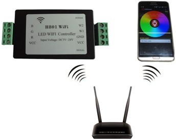
What are the connections on the controller? My understanding is that the WS2812 does not have a separate R/G/B but rather uses a single wire protocol. The strip is using a different type of LEDs, described as “Output RGBWW, 5 routes PWM data”. Is each LED individually addressable (as we need for the clock)?
 .
.