Playing with the ESP-32

As we started to figure out the ESP-32, it was asked how RTC memory works.
One simply uses the RTC_DATA_ATTR attribute on a variable and it will be allocated in RTC memory.

Here is a trivial sketch (yes, we start with the arduino IDE).

#include "esp_deep_sleep.h"

#define led1 17
#define led2 16

void setup() {
  static RTC_DATA_ATTR int led = led1;  // initial state

  pinMode(led, OUTPUT);
  digitalWrite(led, HIGH);    // turn the LED on (HIGH is the voltage level)
  delay(1*1000);              // wait for 1s
  digitalWrite(led, LOW);     // turn the LED off by making the voltage LOW

  led ^= led1^led2;           // kept in RTC memory

  esp_deep_sleep(1*1000000);  // sleep 1s
}

// the loop function runs over and over again forever
void loop() {
}

Attaching a LEDs to GPIO17 and GPIO16, the two will blink in sequence. led keeps its value across the sleep.
Of course we could replace the delay() with a sleep too…

2 Likes

Slightly off topic, how is the Arduino setup going with ESP32? Usable?

So far So good. As you can see, I access the IDF directly in my example.
I only installed it on windows because I have only the laptop with me at the meetings.

1 Like

Another simple example, sending UDP packets. Still using raw IDF API in the arduino IDE.

#include <esp_deep_sleep.h>
#include <esp_wifi.h>
#include <esp_event_loop.h>
#include <sys/socket.h>

#define SLEEP_S   5
#define GRACE_MS  10    // 5ms is too short

static int mysocket;
static struct sockaddr_in remote_addr;
static RTC_DATA_ATTR int n;

static void send_msg(void) {
      char msg[20];

      snprintf (msg, sizeof(msg), "show esp-32a %d", n);
      mysocket = socket(AF_INET, SOCK_DGRAM, 0);
      remote_addr.sin_family = AF_INET;
      remote_addr.sin_port = htons(21883);
      remote_addr.sin_addr.s_addr = inet_addr("192.168.2.7");
      Serial.print(micros());
      Serial.println(" Sending");
      sendto(mysocket, msg, strlen(msg), 0, (struct sockaddr *)&remote_addr, sizeof(remote_addr));
      Serial.print(micros());
      Serial.println(" Sent");
      ++n;
      delay(GRACE_MS);
      esp_deep_sleep(SLEEP_S*1000000);
}

static esp_err_t event_handler(void *ctx, system_event_t *event)
{
    switch(event->event_id) {
    case SYSTEM_EVENT_STA_START:
      Serial.print(micros());
      Serial.println(" SYSTEM_EVENT_STA_START");
      esp_wifi_connect();
      break;
    case SYSTEM_EVENT_STA_CONNECTED:
      Serial.print(micros());
      Serial.println(" SYSTEM_EVENT_STA_CONNECTED");
      break;
    case SYSTEM_EVENT_STA_GOT_IP:
      Serial.print(micros());
      Serial.print(" SYSTEM_EVENT_STA_GOT_IP, got ip: ");
      Serial.println(ip4addr_ntoa(&event->event_info.got_ip.ip_info.ip));
      send_msg();
      break;
    case SYSTEM_EVENT_STA_DISCONNECTED:
      Serial.print(micros());
      Serial.println(" SYSTEM_EVENT_STA_DISCONNECTED");
      esp_wifi_connect();
      break;
    default:
      break;
    }
    return ESP_OK;
}

void setup() {
  Serial.begin(115200);
  Serial.println("");
  Serial.print(micros());
  Serial.println(" Start");

  tcpip_adapter_init();

  esp_event_loop_init(event_handler, NULL);

  wifi_init_config_t cfg = WIFI_INIT_CONFIG_DEFAULT();
  esp_wifi_init(&cfg);

  esp_wifi_set_mode(WIFI_MODE_STA);

  wifi_config_t wifi_config = {
    .sta = {"SSID", "PASS"}
  };
  esp_wifi_set_config(ESP_IF_WIFI_STA, &wifi_config);

  Serial.print(micros());
  Serial.println(" Starting wifi");
  esp_wifi_start();
}

// the loop function runs over and over again forever
void loop() {
  delay(1*1000);
}

At this point the RTC memory item (n) is initialised whenever the program starts (e.g. a reset). We need to find the way to define an uninitialised RTC memory item.
[later] I rewrote this app as plain IDF and had the same problem. I fixed it there by setting a wakeup delay to allow the flash to properly start. I do not know how to set this in the arduino IDE. I set CONFIG_ESP32_DEEP_SLEEP_WAKEUP_DELAY=500 in sdkconfig. For me a setting of 300us or less caused failures, so I selected 500 as a safe delay. The default is zero.

The timing is not great, but this uses DHCP… need to find the function to set IP. Probably similar to the old SDK.
[later] This is now fixed in our repository.

I now put this sketch (udp) in our git repository.
I find that the slow timing is the same if using dhcp or not, which I did not expect.

w/out dhcp:

16525 tcpip_adapter_init
16716 esp_event_loop_init
16792 esp_wifi_init
28017 esp_wifi_set_mode
28149 esp_wifi_start
34701 setup end
106307 SYSTEM_EVENT_STA_START
106359 tcpip_adapter_dhcpc_stop
106450 tcpip_adapter_set_ip_info
106586 esp_wifi_connect
904331 SYSTEM_EVENT_STA_CONNECTED
904397 SYSTEM_EVENT_STA_GOT_IP ip=192.168.2.62 nm=255.255.255.0 gw=192.168.2.7
904773 Sending
905148 Sent

with dhcp:

16575 tcpip_adapter_init
16766 esp_event_loop_init
16844 esp_wifi_init
28023 esp_wifi_set_mode
28151 esp_wifi_start
34736 setup end
106263 SYSTEM_EVENT_STA_START
106314 esp_wifi_connect
960615 SYSTEM_EVENT_STA_CONNECTED
972918 SYSTEM_EVENT_STA_GOT_IP ip=192.168.2.62 nm=255.255.255.0 gw=192.168.2.7
973285 Sending
973590 Sent

The messages precede the described function. Most of the time is spent in esp_wifi_connect.

I am now working with the IDF (rather than arduino IDE). See the project here.

I use gpio17 to mark progress by toggling it at points of interest. It is labeled OUT (pink trace).
I found that GPIO5 is a good marker for the wakeup time so it is used as the DSO trigger. It is the blue trace.

Here is what a common loop of the program looks like:

Clearly this is very much slower than what I get with the esp8266. The whole run takes just under 1.6s.
OUT rises as the app starts, about 250ms after wakeup. The following toggle (~350ms) is when the wifi is started, and much later (at ~1480ms) we see a toggle when we reach STA_CONNECTED. It is followed by a toggle as we senda few 10s of ms later just before we enter deep sleep.

I need to include a current trace to confirm when deep sleep starts and ends.
[later] Got it, the green BAT trace is the current consumed from a 5v battery. GPIO5 looks like a good proxy for “awake”.

It wakes at 60-70mA, rising to around 140mA once wifi is turned on, with short spikes to over 350mA.
Total usage is 204mAs, the esp8266 uses around 50mAs (maybe less, I forget the latest results).

1 Like

I ran the deep sleep led flash example. Interestingly it always fails after quite a few hours. When it fails the last line monitor output is usually:

user code done

I only see this output when the esp32 gets stuck. Pushing reset gets the usual line on a boot.

ets Jun 8 2016 00:22:57

A deep sleep application would not be sufficienly reliable with this failure mode. I expect it occurs because of the known hardware bug in version 0 of the ESP32 which is the one I have.

Perhaps BLE should be used for transmitting occasional sensor data. In this ESP BLE example application the device is awake for about 120ms rather than the 1.6 secs described here with WiFi and 120ms is also better than the esp8266 achieved using WiFi.

Hi Ken,

I ran the deep sleep led flash example. Interestingly it always fails after quite a few hours. When it fails the last line monitor output is usually:

In the “make menuconfig” menu for IDF, try increasing the value “Extra delay in deep sleep wake stub” (under Component Config → ESP32 Specific". The default was recently changed from 1000us to 2000us, as some flash chips (which the ESP32 loads code from during wakeup) take longer to wake up than others.

Thanks @projectgus for the reply. I guess you mean the variable

CONFIG_ESP32_DEEP_SLEEP_WAKEUP_DELAY

in file C:.…\Arduino\hardware\espressif\esp32\tools\sdk\include\config\sdkconfig.h which was already 2000.

I didn’t test this Arduino example again as there was nothing to change.

I tried testing a modified version of the sntp example app with additional logic to alternate between flashing one of two leds for 1 second each wake up with a 1 second deep sleep time giving a cycle time of approximately 2 seconds. It had a

CONFIG_ESP32_DEEP_SLEEP_WAKEUP_DELAY 2000

too. It also failed once after a day or so with the console output being:-

rst:0x5 (DEEPSLEEP_RESET),boot:0x13 (SPI_FAST_FLASH_BOOT)
configsip: 0, SPIWP:0x00
clk_dr

I couldn’t get it to fail again though after testing a further 107,000 deep sleeps so it is rare and behaves differently to the Arduino example.

The time of day values though, were nonsensical. They look about right when the app is started but become nonsensical later. A sample was:

e[0;33mW (891) example: The current date/time in Canberra is: Sun Jun 11 13:24:25 2017
e[0;33mW (891) example: The current date/time in Canberra is: Sun Jun 11 13:25:55 2017
e[0;33mW (891) example: The current date/time in Canberra is: Sun Jun 11 13:25:37 2017
e[0;33mW (891) example: The current date/time in Canberra is: Sun Jun 11 13:24:58 2017
e[0;33mW (891) example: The current date/time in Canberra is: Sun Jun 11 13:24:46 2017
e[0;33mW (891) example: The current date/time in Canberra is: Sun Jun 11 13:25:34 2017
e[0;33mW (891) example: The current date/time in Canberra is: Sun Jun 11 13:29:06 2017
e[0;33mW (891) example: The current date/time in Canberra is: Sun Jun 11 13:29:52 2017

The time of day is changing by minutes and going backwards and forward when the cycle is approximately 2 seconds. The date was also wrong being the date the test was started even though it was 3 days previous. I guess this is part of the problem documented on the espressif forum.

Previously I referenced a claim that the time required to wake from deep sleep send a message and sleep again with BLE was 120 milliseconds. This can’t be the case when @eyal found the user app doesn’t start until 250 milliseconds after wake up. BLE sensors e.g. bicycle cadence sensors, heart rate sensors, etc run for months on a single button battery. Due to the long boot time the ESP32 would consume too much energy for that.

Looking at the potential to reduce the boot time. Boot is in two stages. The first stage runs from ROM and can’t be changed. Stage 2 starts at 14 milliseconds and takes a long time. The second stage is not required as espressif advises:

“It is possible to write a fully featured application which would work when flashed to offset 0x1000”

which is the normal second stage boot loader address but much of what the boot loader does would have to be done by the application so it is uncertain how much time can be saved. For example WiFi requires quite a lot of code to be loaded and just commenting out line 90 obtain_time(); which removes loading the WiFi code reduces startup time by 260 ms to 601 ms with the extra time being consumed in the

boot: Loading app partition at offset 00010000

step. I can’t get the 250ms boot time reported by @eyal.

I wonder why?

Yes @Ken_Taylor, the clock is bad right now. To get something sane you can use the RTC clock which runs from initial boot/reset (also during sleep).

uint64_t my_time_us (void)
{
    uint64_t rtc_time_get(void);  // RTC 150KHz tick count

    return rtc_time_get() * 20 / 3;  // ticks -> us 1,000,000/150,000
}

The rate is not accurate (slightly different for each module) and it changes with the temperature.

HTH

Edit: This is in references to the rate not being accurate, not the rest of the issues…

Sounds like they just need to put a 32k crystal on the RTC oscillator. From the hardware design guide it supports it (capture below). Then you’d have a crystal for the main oscillator and RTC, so you’d be within about 10ppm without calibration (which is about 1 min per month drift).

I’m still waiting on some ESP32’s to turn up. Once I’ve got my hands on one I’ll see if I can hack a crystal on the board, it’ll depend on what else has been put on those pins though…

GPIO 32/33 are two (of the 8) ADC inputs. I use them :frowning:

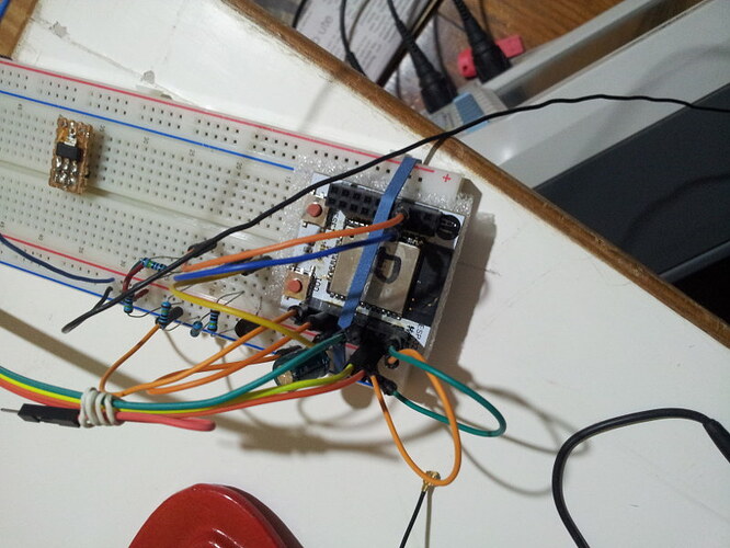
I have two modules and you can have one to experiment with. It is mounted on a plate with female pins on top instead of the provided male ones.

[OT]
BTW @Harvs, at the top-left is one of your DC-DC modules using the 1825S. The doco says 500mA but the esp dies the moment the wifi is turned on. Tested with fully charged 3xAA and Li-Ion.

I (541) wifi: wifi firmware version: 41eede3
I (541) wifi: config NVS flash: enabled
I (541) wifi: config nano formating: disabled
I (551) whfi: Init dynamic tx buffer num: 32
I (551) wifi: Init dynamic rx buffer num: 32
I (551) wifi: wifi driver task: 3ffb8824, prio:23, stack:4096
I (551) wifi: Init static rx buffer num: 10
I (561) wifi: Init dynamic rx buffer num: 32
I (561) wifi: Init rx ampdu len mblock:7
I (561) wifi: Init lldesc rx ampdu entry mblock:4
I (571) wifi: wifi power manager task: 0x3ffc4a24 prio: 21 stack: 2560
  0.090245 esp_wifi_set_mode
  0.104057 esp_wifi_set_config
  0.104279 esp_wifi_start
I (591) wifi: wifi timer task: 3ffc5aa4, prio:22, stack:3584
k<D6>'nw6jrf^Bvrrwr<A7>rbr<B7>r<F3>v
Guru MeditAtion Error of type IllegAlInstruction occurred ol co2e  1^N Exception was unhandled.
Register dump:
PC      : 0x400f4ec0  PS      : 0x00060c30  A0      : 0x800f8ac8  A1    ^@ : 0x3ffbd4c0  
A2      : 0x3ff`5ba8  A3      : 0x3ffbd510  A4      : 0x00000059  A5      : 0x00000002  
A6      : 0x3fFb1364  A7      : 0x400824c4  A8      : 0x800f4ec0  A9      : 0x3ffbd480  
A10     : 0h00000000  A11     : 0x3ffbd^U10  A12     : 0x3ffaf580  A13     : 0x00000000  
A14     : 0x00000001  A15     : 0x000&0023  SAR     : 0x00000000  EXCBAUSE2 0x00000000  
EXCVADDR: 0x00000000  LBEG    : 0x4000c2e0  LEND  ^@ : 0x4000c2f6  LAOUNT  : 0x0000^P000  

Backtrace: 0x400f4ec0:0x3ffbd4c0 0x400f8ac8:0x3ff`d4f0 0x400f5107:0x3ffbd510

Rebooting...

None of my “ftdi” modules can handle it either. It does however run well directly from a LiFePO4 or, of course, from a PS.
On the DSO I saw it usually peaking (for a ms or two) at just under 500mA, and rarely just over. Maybe a large cap can help on the battery side (there is a 470uF on the Vdd).
[/OT]

It’s a bit unfortunate that for such a capable processor with so many peripherals, they only put in it a QFN-48 package. I think it could have been more generically usable if they had opted for one of the larger packages (64 pin or larger) and multiplexed more pins.

However I guess at the price of the ESP32 (and the ESP8266), the cost of packaging the die is probably significant.

I’ll do a bit of investigation into the power side of things when I get my hands on one. Despite the max rating of the LDO looking to be high enough, it’s likely the LDO’s transient response isn’t fast enough to keep up.

I might take you up on the offer of borrowing one if none of the ones I ordered have turned up by Wednesday. I’m still finishing up with the ESP8266 boards at the moment…

1 Like

When are we making powerful robots with these ?

ADC can measure voltages on 18 pins according to Section 4.2 of the ESP32 Datasheet so losing 2 to a chrystal is not too bad.

@Ken_Taylor, not so fast :-)

ATM the IDF implements only one of the two ADCs (each handles 8 pins). See here.

@Ken_Taylor
For the record, I accidentally started an esp32 after a flash erase (the actual flash did not happen). The messages I received are:

E (13) boot: nothing to load
user code done

A useful clue.

I didn’t see

E (13) boot: nothing to load

and if reading from flash fails we should see the basic interpreter so I guess

user code done

with nothing else is what happens when flash read works but data read from flash is erronous. Wouldn’t it be better if the device rebooted after generating the message

user code done

?

I’m also wondering why the boot is so much longer in the modified sntp example (according to the debug message timestamps) than the 250 ms @eyal measured.

Now that Espressif has fixed the nonsensical date/time functions, drift over multiple deep sleep cycles can be measured. As mentioned at last nights meeting, running the modified sntp example code with a cycle time of 2 secs and 50% of the time asleep I got -18 secs over 13500 cycles taking 8.5 hours overnight and +7 secs over 1100 cycles and 42 mins in the morning with the room heater on. This drift is high for some use cases.

At the meeting there was speculation on what the drift would be if not using deep sleep. I checked and over 9 hours saw no observable drift.

Testing in all cases was by visually comparing the clock on an Android phone.

1 Like