Here’s another project I’ve put together recently, largely stemming from an oversupply of signal relays.
For those that haven’t seen them before, most of the major test equipment manufacturers have scanning meters, or external scanners that use one of their meters. The idea is pretty simple, relays just run through a programmable sequence of connecting the meter to inputs, then record the meter’s output for each input.
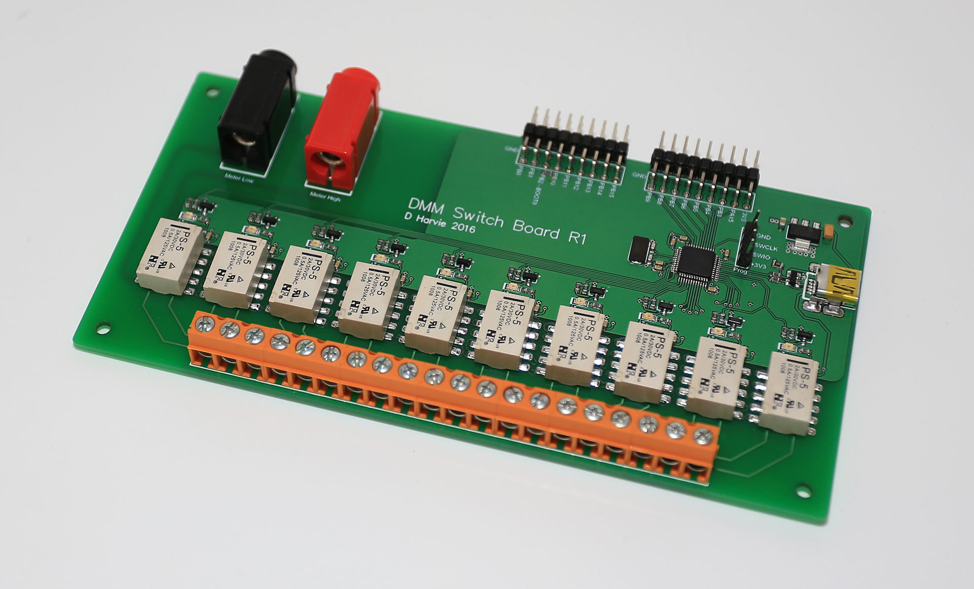
So this one is a 10 channel, USB connected scanning card which you control from a PC. The idea being that you can take any old meter that you can read the output to a PC, then control the card to take measurements.
Very useful when you have a whole bunch of test points and one expensive meter. Also great when you’re trying to make relative measurement (such as input to output efficiency), where absolute accuracy is less important that ratios.
I’ll post all the source to Github once I’ve verified there are no mistakes at the hardware level.
Relays are spec’d for 10^8 actuation’s, which is pretty similar to the relays in the commercial units.
I did some testing on the switch speed and got figures of 1 ms to close and 2ms to open (until all contact bouncing had stopped.) Which is similar to the spec’s on the Keithley 2000 series cards.
I’ve brought out all the GPIO as it should be easy to communicate with a GPIB meter directly.
As for the logo, I couldn’t find an Altium version with a quick search, and I didn’t have the time to muck around importing SVG files. It can be done, but it never goes smoothly.
I downloaded the one that obviously has the logo, but it’s the usual conversion from raster to lines on the silkscreen. Usually ends up looking pretty rubbish when made.
Some time I’ll convert a line drawing which come out a lot better on silkscreen.
But I don’t see it as a big thing. All the files are there, and the logo on the schematics say everything to do with the project is basically in the public domain.
Added some python scripts for using an Agilent U12xx meter with the board.
In future I may get around to hooking up the GPIO to a GPIB connector so it can interface directly with some old HP meters I’ve got. But otherwise this is pretty much complete.
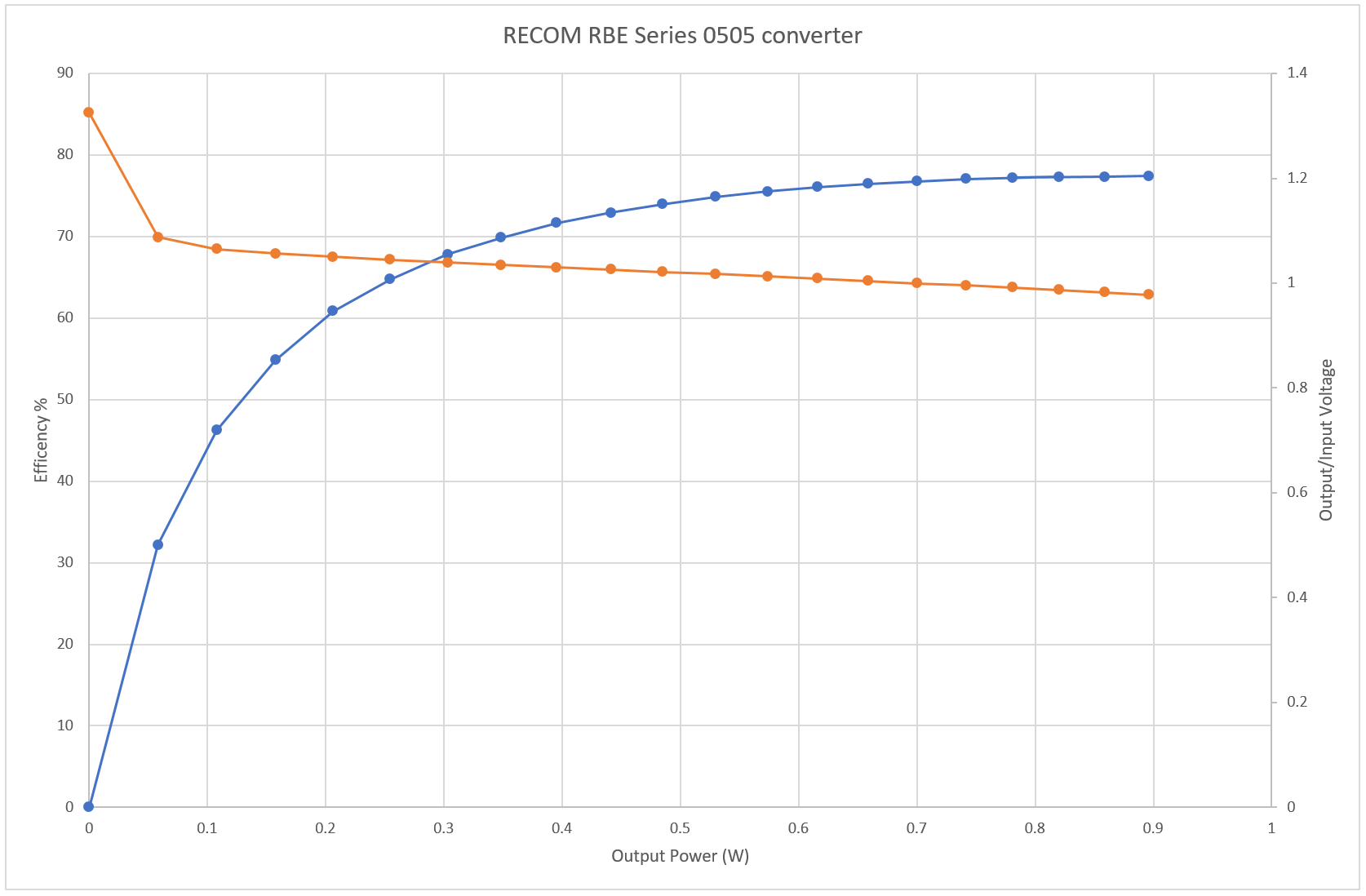
This is from one of the examples checked in, scanning the input and output currents and voltages of a small DC-DC converter under varying load.