ESP8266 Deep Sleep Cycle Times and Power Consumption With WiFi On

This time with WiFi On. Using Arduino IDE rather than lua.

I failed to do the simplest test so far. Using a Wemos D1 Mini.

#include <ESP8266WiFi.h>

#define TIME_PIN  13  // D7=GPIO13
#define SLEEP_MS  500

static void do_stuff()
{
  byte status;

  Serial.begin(115200);
  Serial.println("");

  WiFi.begin("ssid", "pass");
  byte i = 10; // 5 seconds timeout
  while ((status = WiFi.status()) != WL_CONNECTED) {
    delay(500);
    Serial.print(status);
    if (--i <= 0) {
      Serial.println(" no WiFi");
      return;
    }
  }

  Serial.println(" have WiFi");
}

void setup() {
  pinMode(TIME_PIN, OUTPUT);
  digitalWrite(TIME_PIN, LOW);

  do_stuff();

  digitalWrite(TIME_PIN, HIGH);
  delay(1);
  digitalWrite(TIME_PIN, LOW);

// WAKE_RF_DEFAULT, WAKE_RFCAL, WAKE_NO_RFCAL, WAKE_RF_DISABLED
  ESP.deepSleep(SLEEP_MS*1000, WAKE_RF_DEFAULT);
}

void loop() {
  // sleeping so wont get here
}

The TIME_PIN is used to mark the start and end of the program.

All I get is a repetition of
0000000000 no WiFi
with the occasional crash:

0000000000000
Exception (0):
epc1=0x40217a7f epc2=0x00000000 epc3=0x00000000 excvaddr=0x00000000 depc=0x00000000

ctx: sys
sp: 3ffff670 end: 3fffffb0 offset: 01a0

>>>stack>>>
3ffff810:  40104c21 40104c1e 00000000 00000001
3ffff820:  400005e1 92104ba0 00000000 00006a4e
3ffff830:  40217a7f 00000033 0000001b ffffffff
.... many  more of this
3fffff70:  3ffec530 3ffe9370 3fffdcc0 3ffe8b00
3fffff80:  00000040 3ffec530 00000000 3fffdcb0
3fffff90:  40203fd7 3fffdab0 00000000 4020274b
3fffffa0:  3ffe8b00 40000f49 3fffdab0 40000f49
<<<stack<<<

 ets Jan  8 2013,rst cause:2, boot mode:(1,6)


 ets Jan  8 2013,rst cause:4, boot mode:(1,6)

wdt reset

Adding yield() in places makes no difference. It happens often but not every time.

Anyway, the 0 status indicates that nothing WiFi happened so far. I expected it to at least to progress to 1 if not further. I will only send a UDP packet so no need to establish a connection.

Looking at the power usage shows that the WiFi engine does start before the program starts.
1 Like

Some progress… I flashed the module with the lua image and checked that it connects to the AP. No problem.
I then flashed the Arduino image (just using the IDE) and now it does connect. I swear I did the same a few times before!

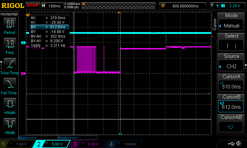
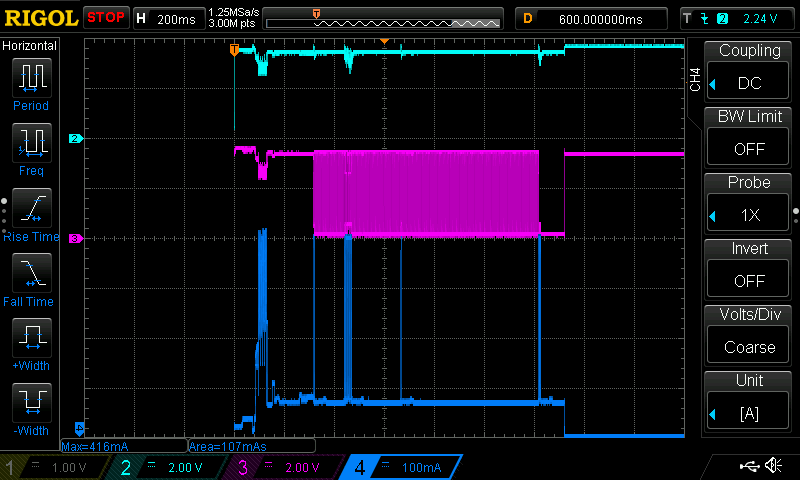
Anyway, it now reports that it takes 820-900ms to get a connection, I hope it can do better. It also uses much energy in the cycle. Here is a capture of one such cycle

The max current is 416mA, higher that usual, but the source was supplying 3.5v rather than 3.3v so maybe there is a relation. It surely wanted a lot of power, a few other USB/TTL adapters could not handle it.

Timewise we see just over 300ms from reset to program start, followed by under 900ms of waiting for access to the AP. Entering deep sleep measures about 100ms.

This program is a slightly modified as it loops waiting for WiFi while toggling ch3(pink) once a ms. It would be identical to the earlier program without the bling.

#include <ESP8266WiFi.h>

#define TIME_PIN        14  // D5=GPIO14
#define SLEEP_MS        500
#define WIFI_WAIT_MS    1
#define WIFI_TIMEOUT_MS (10*1000)

static byte level = 0;  // LOW
static void toggle()
{
  digitalWrite(TIME_PIN, (level = ~level) ? HIGH : LOW);
}

static void do_stuff()
{
  Serial.begin(115200);
  Serial.println("");

  toggle();
//WiFi.begin("SSID", "passphrase");
  int i = WIFI_TIMEOUT_MS;
  byte wstatus;
  byte old_wstatus = 100;
  Serial.print(WL_CONNECTED);
  Serial.print(": ");
  while ((wstatus = WiFi.status()) != WL_CONNECTED) {
    if (old_wstatus != wstatus) {
      Serial.print(wstatus);
      old_wstatus = wstatus;
    }
    toggle();
    delay(WIFI_WAIT_MS);
    if ((i -= WIFI_WAIT_MS) <= 0) {
      Serial.println(" no WiFi");
      return;
    }
  }

  Serial.print(" have WiFi in ");
  Serial.print(WIFI_TIMEOUT_MS-i);
  Serial.println("ms");
}

void setup() {
  pinMode(TIME_PIN, OUTPUT);
  digitalWrite(TIME_PIN, LOW);timing_and_temp.ino
  level = 0;

  do_stuff();
//delay(1);           // dummy program

  digitalWrite(TIME_PIN, HIGH);
  delay(1);
  digitalWrite(TIME_PIN, LOW);

// WAKE_RF_DEFAULT, WAKE_RFCAL, WAKE_NO_RFCAL, WAKE_RF_DISABLED
  ESP.deepSleep(SLEEP_MS*1000, WAKE_RF_DEFAULT);
}

void loop() {
  // sleeping so wont get here
}

Once the AP credentials were given it was not necessary to repeat, it auto-connects.

My plan is to compare the performance of the same program on the same ESP8266 module implemented with

  • NodeMCU LUA
  • SDK (no-os)
  • SDK (rtos)
  • Arduino

I seem to be the only one in this room… never mind.

I now have a working sketch, checked it in here.

Not too bad. Here is a timing trace

The trigger is at the left margin, the program starts at 310ms, ends at 500ms and deep sleep starts at around 620ms.
There is a gap of about 100ms from the program end (the last single bleep) and deep sleep. There is also a 50ms gap before it, this is an explicit delay. Not doing this will cause any pending UDP packets to not be sent. I consider this an SDK bug.

The first thing the program does is read the ds18b20. It takes 18ms and this is the initial gap. Then there is a run of toggles, 1ms apart, while a waiting for wifi to connect, after which the UDP packet is sent.

Because it takes a while for wifi to become available, it is a good idea to do other things while waiting, in this case reading the ds18b20. I expect it includes some idle time that the wifi can use to get going in the background.

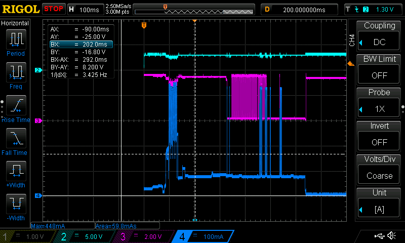
Here is a trace showing the power usage.

It is not the greatest, at about 60mAs, but a good start. The peaks are significant (at 450mA) and the power supply is stressed (as the deeps in ch2 and ch3 show when the peaks happen). Power is supplied from a power bank through an FTDI (probably fake).

The UDP messages look like this:

  show d1-mini times=s0.262,u0.000,r0.018,w0.149,t0.150 21.8750

This format is close to what I use with sensors around the house. The times are:

  s0.262 time reported at program start (262ms)
  r0.018 time to read the ds18 (18ms)
         it takes place inside the wifi waiting time
  w0.149 time waiting for wifi, from wifi setup (149ms)
  t0.150 total time (from program start) (150ms)
  21.8750 the reported temperature

All times from micros() and displayed as sec.ms.

I now completed the main body of the sketch, it is much more similar to the lua version. The missing parts are not important for this comparo.

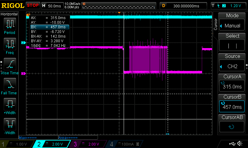
This is what the timing looks like now

The program thinks (and reports) a run time of 142ms (BX-AX). The wakeup sequence is 315ms(AX) long. The shutdown is about 110ms. Power was not measured but I expect it to be similar to what was seen above.

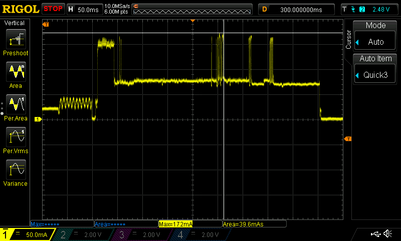
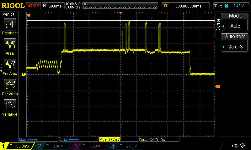
Captured traces with and without RFCAL. This is on an ESP-202 powered from one Li-Ion battery through a MCP1700 LDO. The DSO is measuring the voltage across a 1R resistor in the battery ground wire.

A wakeup with RFCAL

And one without RFCAL

The calibration phase is clearly visible around 120ms into the wakeup (about 30ms long), and the full cycle is longer by about the same 30ms. The power consumption is up 4.5mAs.

I note that this module seems to use less power (172mA max) than I experienced before (around 400mA). I need to test other modules to see if this is related.

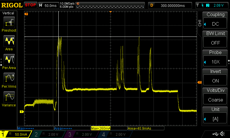
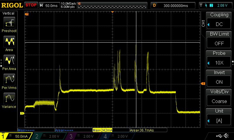
The battery measures 4.13v during deep sleep and 3.70v during activity. Changing yo an ESP-12E (this board uses an ASM1117 LDO which consumed 2-3mA itself).

A wakeup with RFCAL

And one without RFCAL

Very different. Not only the power usage is higher but it has a different pattern. Also the power rise/fall (see the start/end of the cycle) is very fast in the 202 compared to the 12E. Is this the LDO? The ESP?

I tested an ESP-12F with a MCP1700 LDO and I saw traces similar to the ESP-12E.
I also tried 3*AA NiMH with no change.
Everything done with a recent (18/Aug/16) dev SDK branch.

Is this the ESP-12 itself? Some internal parameters?

Ideally you want to be measuring this sort of data between the device and any bulk storage or LDO, as any bulk storage caps will low pass filter the current, and the LDO as an internal opamp that as a transient response. The difference in shape (the “squareness”) will largely be the transient response of the LDO.

The actual timing and duration however will be a function of ESP.

Agreed @Harvs,

I expected so. but I saw the same (slow) response with both LDOs. Here is a summary of the above report:

  • esp-202 with MCP1700 - fast
  • esp-12e with AMS1117 - slow
  • esp-12e with MCP1700 - slow

The first two use identical PCBs, the third is a breadboard.
In all cases there is a 470uF cap across the esp power pins.
I also measured the power on the ground wire (3.3v) from the LDO to the ESP with same results. This was done on the breadboard.

BTW, I understand that the esp-202 is just the latest incarnation of the ESP-12E/F.
Nevertheless, if you happen to be around (one Wednesday) I would like to take the proper measurement.

I should be able to make it in tomorrow evening if you’re around (and the space is open?)

Could be something else as well, e.g. is there a ferrite bead in the power path?

Generally though as a design goal you do what you can to not to have fast edges on the power lines leaving the board, as it causes the wires to radiate and causes all sorts of EMI/EMC issues.

I plan to be there, and expect the space will be open (fingers crossed).

There is a claim in this Github discussion relating to connection times that connections can be established faster if you specify BSSID and channel rather than SSID.

This seems a good idea, have you tried it @eyal ?

No, never tried this. However, my connection is faster than anything mentioned there.
Anyway, I do not trust the timer, I check timing on the DSO.
I need to check the timing I get today, as I did improve it a bit since.

RFCALwise, I do it every 10 cycles but it is only needed if the situation changes (probably if it starts raining?).

@eyal yes, there is some inconsistencies which I wondered about at https://github.com/tzapu/WiFiManager/issues/221#issuecomment-258298987 .