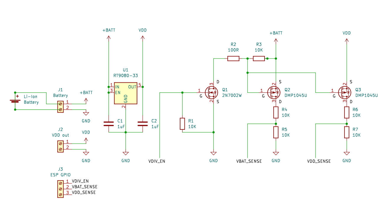
I decided to implement a better way to measure voltage. Until now I simply use a voltage divider into an analogue input. Since it is permanently active I had to use high resistances (1m+1m). Derryn used FETs to turn the dividers on/off which uses very little power for a very short time so a much lower resistance is required. I am now using this approach where I need to measure three different voltages. You can see DDerryn’s schematics on page 2.
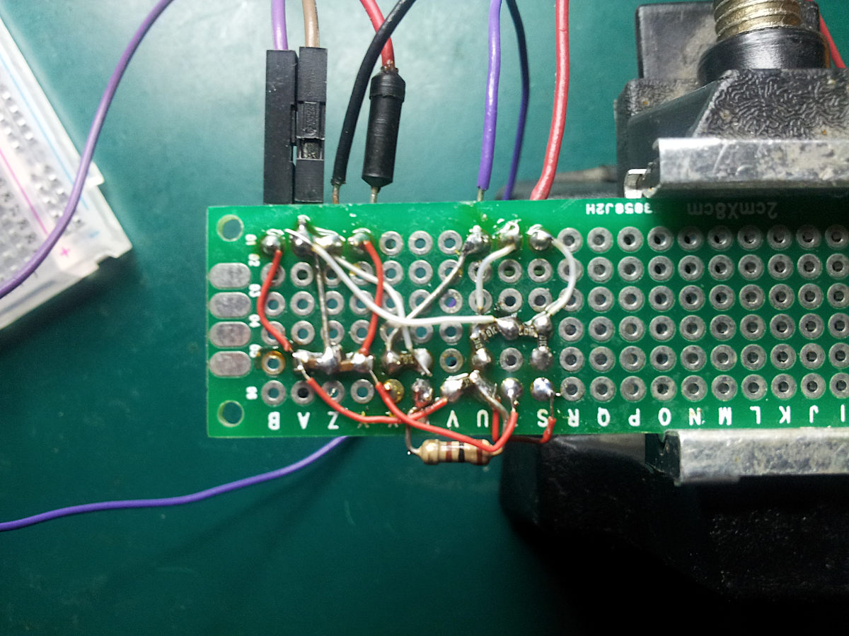
Here is my first ugly first attempt it looks now (just a POC).

This is what I put in discord:
I finally decided how to put everything together, and took one 2N7002 out to solder on the sot23 carrier that I have. Does not fit... finding the exact datasheet (2N7002W) I now see that it is actually a sot323, so 0.65mm pitch rather than 0.95mm. The back side of my sot23 carrier has 0.5mm pitch mounting so I kind-of soldered onto it. I think it will work. [later] It works. For the sot323 device, I used the 0.5mm adapter, flooding all 5 tracks with solder, on both sides, then separating the G/S tracks with a flick of the iron. Ugly but works reliably. Measured the current when off and it is about 3-4nA, so very good. Uses about 1.2mA when on. Next I will see if I can drive two P-channel FETs from the same N-channel FET. [even later] Added a second P-channel directly connected to the gate of the first. Seems to work.
To be continued.