Hi all, thought I’d drop this here (A good way to keep me on my toes)
I was working on recreating a OSI 300 6502 trainer, and a generous benefactor noticed, and brought in the real thing.
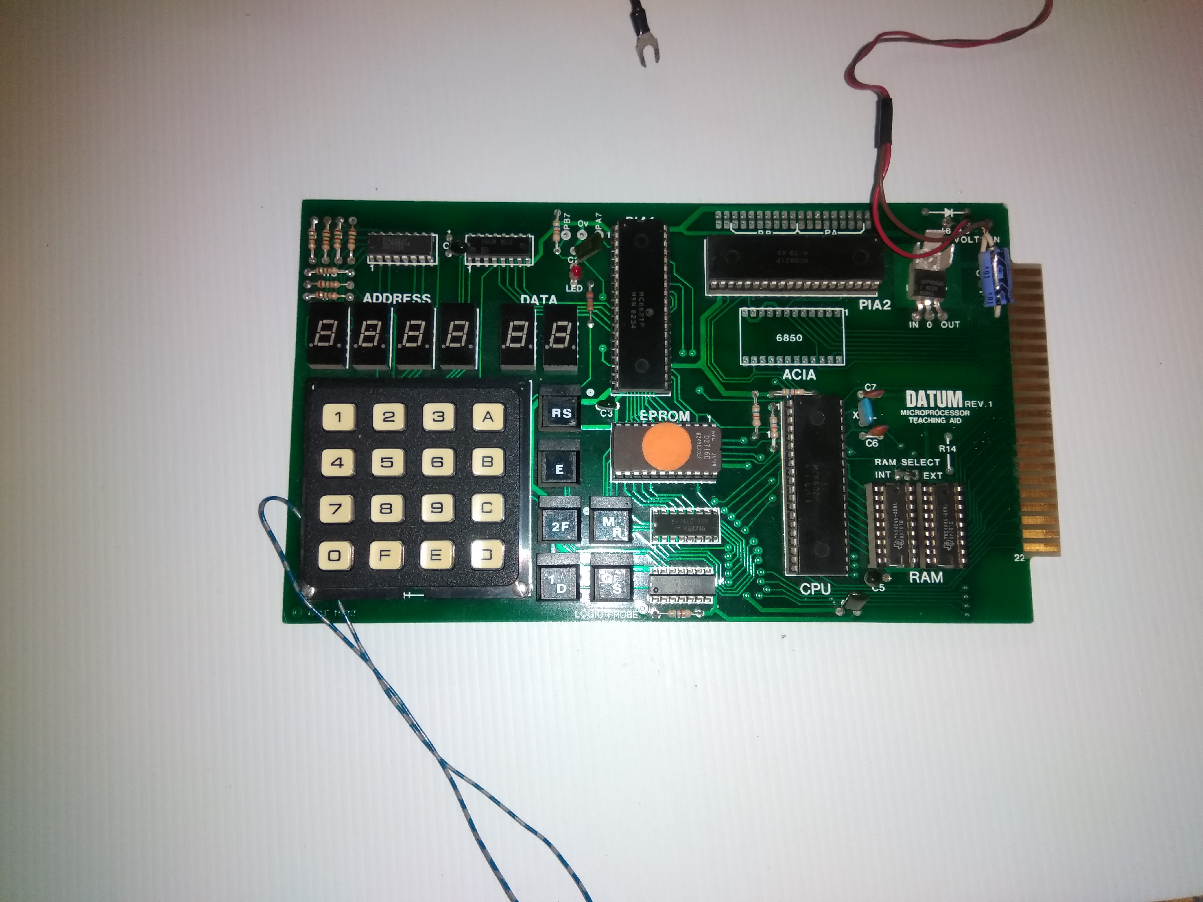
A 6802 digital microprocessor trainer (Interesting to see it labeled a microprocessor trainer, rather than most other being called digital logic trainer, even though they’re really the former.
I did a bit of digging, and from the original product advertisement I found the name of a guide, from searching that I found the following: Lots of PDF’s
It seems one of the original designers donated a large number of the original manuals to the site, however the digitised copies are only accessible to members, and member sign-up is restricted (story of my life).
I’ll try and see if I can get in contact with anyone on the site, but that’s where we are for now.
Some pics:
Hi,
I may be nitpicking here but a 6502 is a different beast to the 6802.
Am curious about the users manual. These kind of boards were popular in the 80’s. In general they had a rudimentary system monitor program running in ROM and you’d enter small sample programs from the keypad.
Perhaps I was a little vauge, no, the 6502 and 6802 are absolutely different beasts, that’s hardly nitpicking.
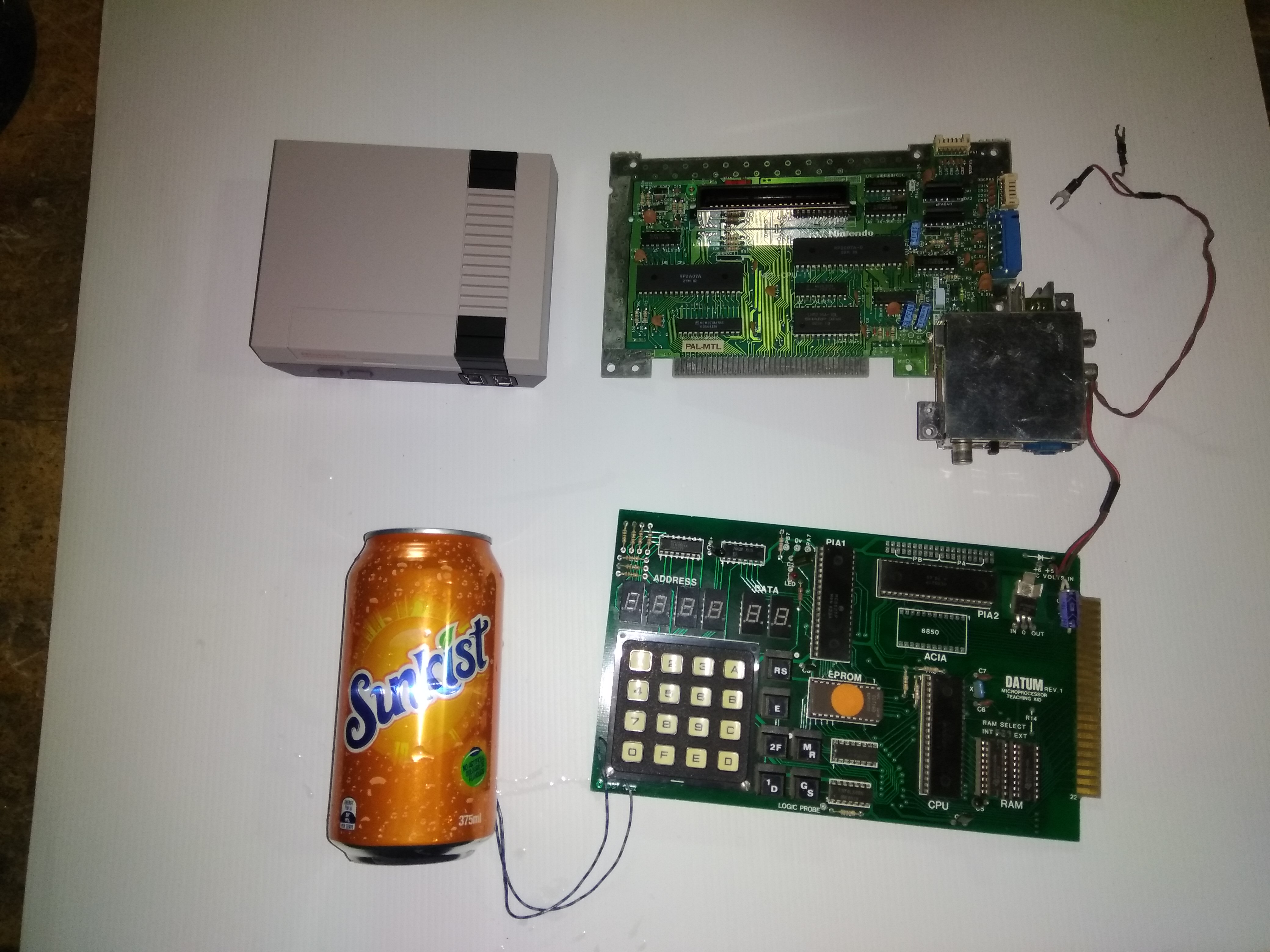
I was working on my own 6502 trainer based on an old American design, the one brought in by (username goes here) is totally different, in nearly every way possible. Different architecture (so I’m lost without the original manual, I know my way around the 6502 enough that if it used one, I’d probably be able to work it out, but I’m totally clueless when it comes to 6800’s), additionally this one has a hex keypad and 7-segment display, PROM, and a massive edge connector, and on top of that, it’s made in Australia (insert patriotic noises here).
The 6502 design I’m recreating just has RAM, toggle switches and LED’s, a much simpler design using a much simpler chip.
It’s an interesting contrast between a digital trainer designed in, I think, 1976 (the 6502 board) and 1982 (the Australian 6802 pictured).
I was going to make another thread for the 6502 board, but I might as well just post about it here (once the parts arrive) how many threads about digital trainers do we need, really?
Anyway, here’s hoping I can get that manual, and project ideas for it are welcome. No point having a gorgeous board like this if it’s not in a nice housing doing something interesting
(Maybe we could frame it with the first gen Pi with the silkscreen typos)
Based on the 6802 data sheet and the board components much of the schematic will be straight forward. The data bus (D7-0) will route directly to the PIAs, ACIA, RAM, ROM and card edge. Address lines most likely are - A9-0 -> ROM, A8?-0 -> RAM, A15-0 -> card edge. A1-0 probably route to PIA RS1-0 and A0 to ACIA RS0. Am not sure if the 74138 is being used to decode memory addresses or for keyboard scanning. Chasing out the chip select inputs for the ROM, PIAs and ACIA will help. The PIAs have 3 chip select inputs, these may be connected to 1) an address line e.g. A15, 2) '138 output pin or 3) power/ground.
A while back I got bored and wrote a 6502 disassembler in Java. Don’t imagine it would take too much work to convert it to 6800.