Anyone williong to hep with some basic electronics

I am attempting to make a static electricity generator for a mate to use to make model grass stand up.

So I built this voltage doubler thing with diodes and capacitors, and it works great when I plug it directly into the mains. Static electricty things happen, big fat spark off the end when I discharged it, and nothing blew up or caught fire.

(can’t put images in posts. See //upload.wikimedia.org/wikipedia/en/thumb/c/ca/Full-wave_Villard_cascade.svg/600px-Full-wave_Villard_cascade.svg.png
//paulmurray.files.wordpress.com/2016/02/static.jpg
)

However, my mate is not willing to plug anything I build into the mains in his house, and I respect that. Even though it wasn’t me who nearly burned his house down last time we built something. It has to run off a battery.

So. To power this thing, I need some sort of oscillator. I got on wikipedia and found the description of a multivibrator, and that seems to be the go. A visit to Jaycar and a bag of assorted transistors and capacitors later, and I am having some success but I am not managing to make the damn thing oscillate. I managed to get a transistor turning an LED on and off. I hooked up some capacitors and got the led turning off when I touched the lead and then fading back into full brightness, which was cool. I hooked two transistors together in a pair and the thing was so sensitive if I touched one of the leads the led would switch.

But it won’t oscillate.

I’m working off this diagram here:

://upload.wikimedia.org/wikipedia/commons/thumb/6/6a/Transistor_Multivibrator.svg/220px-Transistor_Multivibrator.svg.png

Can’t for the life of me figure out what resistors r1 and r4 do. They go to the collector, so I’m guessing that they are the actual loads. I use some 220nF caps for c1 and c2, and 4.7M resistors for r2 and r3, which should make it blink slow enough that I can see what’s going on. I am not going to run out and get an oscilliscope at this stage.

My problems are:
Where do I stick the leads going into the voltage multiplier? Do I put them in in place of R1 and R2? Do I put them across a resistor and that gets put somewhere? (my other problem is polarity - I might need to grab the opposite transistors and reverse things - not really keen on the idea of desoldering all those diodes).

What are suitable values for the resistors? I’m suspecting that the reason I’m not seeing oscillation is that I’m using such a high resistance for r2/r3 that it won’t drive the transistors properly.

I’m not quite at the stage where I’m ready to lay out cash for an oscilliscope.

I can put my gear in a bucket and bring it to MHV or anywhere, I’d be happy for someone to fly over Curtin here and have a look.

Would someone be willing to have a look at this thing?

I use some 220nF caps for c1 and c2, and 4.7M resistors for r2 and r3, which should make it blink slow enough that I can see what’s going on.

This is a transistor bias current issue. Assuming 0.7V Emitter-base voltage drop, you’ve got 4.3V and 4.7M ohms. Remembering ohms law, that’s 4.3/4.7E6=0.9uA delivered to the base of the transistor to turn it on. It’s been a very long time since I had to know how to apply hfe gain numbers in these situations but pretending that you’ve got NPN transistors with hfe=100-ish, and ignoring all the real complexities (DC gain != AC small signal gain; hfe is an active mode number [I think?] but multivibrators are driven well into saturation [IIRC?]) - that probably make this calculation worthless, we get an “on” current contribution from R2 &R3 of… roughly 90uA. Obviously in order to get a LED to light up; your capacitors must also be contributing some current, or I’ve just calculated the transistor gain wrong.

But the moral of the story is, don’t use such large resistor values. Increase your capacitor values instead - go for uF caps and kohm resistors so that the transistors will be able to actually conduct a useful amount of current when they’re on.

There are other, more efficient ways to skin this cat (inductors are your friends! that’s why old CRT displays used big flyback transformers to generate a steady 30,000V or so in your old TVs), but that’s my long-winded explanation of why your multi-vibrator isn’t driving bigger loads.

Whether this will work as a source for your voltage multiplier is another story. If you want to stay on this design, you may need to make your multivibrator outputs drive another pair of intermediate beefy transistors or FETs or something that can deliver a much more serious amount of current.

Forgot to add:

I’m not quite at the stage where I’m ready to lay out cash for an oscilliscope.

I can put my gear in a bucket and bring it to MHV or anywhere, I’d be happy for someone to fly over Curtin here and have a look.

Would someone be willing to have a look at this thing?

MHV is the perfect space for this :slight_smile: We have oscilloscopes, function generators, and stuff!

You’re welcome to come along any Tuesday or drop in on @ManicDee & the crew on Electronics Wednesdays.

Tuesday or Wednesday. Will do.

Well I expect to be there on Tuesday night and happy to “help”

Owen

1 Like

What frequency are you trying to generate? I’m just thinking it might be easier to do with some type of processor, like an ESP8266-01, perhaps.

Here’s a very simple oscilator that I wrote in LUA, just set the interval time in miliseconds to variable intervalms

-- Simple pulse generator.
coilOut = 3
dwellTime = 4
intervalms = 200

gpio.mode(coilOut,gpio.OUTPUT)

function coilOff()
    gpio.write(coilOut,gpio.LOW)  
end

function coilOn()
    gpio.write(coilOut,gpio.HIGH)
end

tmr.alarm(0,intervalms,1,function()
    coilOn()
    tmr.alarm(1,dwellTime,0,function()
      coilOff()
    end)  
end)
1 Like

My old analog electronics lecturer always shook his head when we proposed microcontrollers for such things :slight_smile:

But I agree, it’s certainly a decent (and perhaps fun, if you’re a software person) solution. Software-defined oscillator? :smiley: You might even be able to use the duty cycle to fine-tune the voltage over WiFi.
For me, this guy holds the benchmark in advanced high-voltage systems (definitely not basic though)

Although, regular society did a lot to chase him away and he now lives in a mobile van.

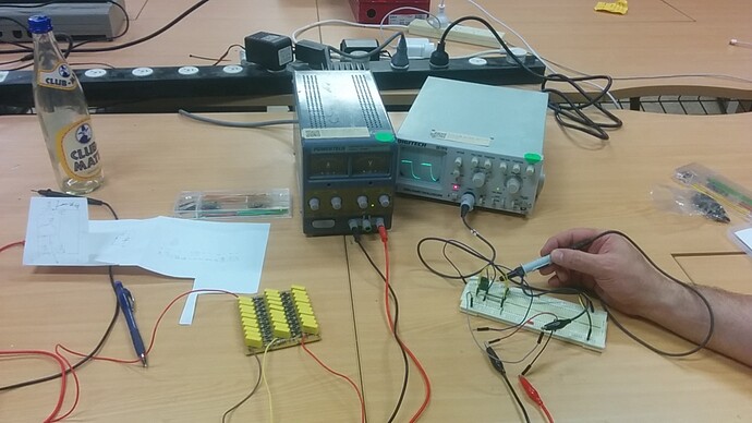
Last night’s debugging: