Following yesterday’s “Things Night” discussion I checked the misbehaving esp-07 setup. I have two deployed, one has stable power (around 3.3v at all times) while the other sees 3.3v in deep sleep but only 2.9v (or below) when it wakes up. Both use the same type of LDO.
I replaced some hookup wires and also provided direct connection from the LDO to the esp (bypassing the power rails). This made a (positive) difference and I now see around 3.3v reported instead of the 2.9v. I hope it will now stay stable.
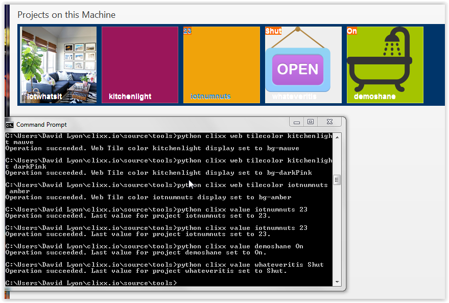
Last time @Eyal, you mentioned you were sending UDP packets. I’ve worked out a way to display the values from such packets in the top-left-corner of the device tiles in a web interface.
The data sent (using UDP or TCP) is a simple text string. Most of it is debug and stats but the last field is the reading (temperature). The server does not care what the text includes so any device sending text is catered for.
The app itself is not really production ready as it includes too much configuration and test fluff. I will trim it down once I am done with it but I am waiting for the v1.2.0 release of the fw which is in early development.
For example, this message
store esp-12e 17908 times=L4.570,T30177,s0.617,u0.323,r0.709,w1.885,F0.000,S0.016,d0.934,t3.924 stats=fs5,fh0,fr0 adc=1.176 vdd=2.854 21.5000,21.8125
tells the server (a simple python script) to store, from device ‘esp-12e’, the provided text. The server writes to a per-device file with an added time-stamp. This device has two ds18b20 sensors reading 21.5000,21.8125 (yes, I keep my workroom warm, the ouside facing sensor is reading 5.7500 now). Right now there are nine devices being tested around the house.
This is all in our github (my app_v1). Has it been two months really? maybe I should update it… But in my defence, one of my tests has been running for two months now on 3xAA so it is running this old code.
I’ll have to package up the program and finish off the documentation so that it’s a bit easier to install. I will be doing that at work today. I will post back a download link when that’s done.
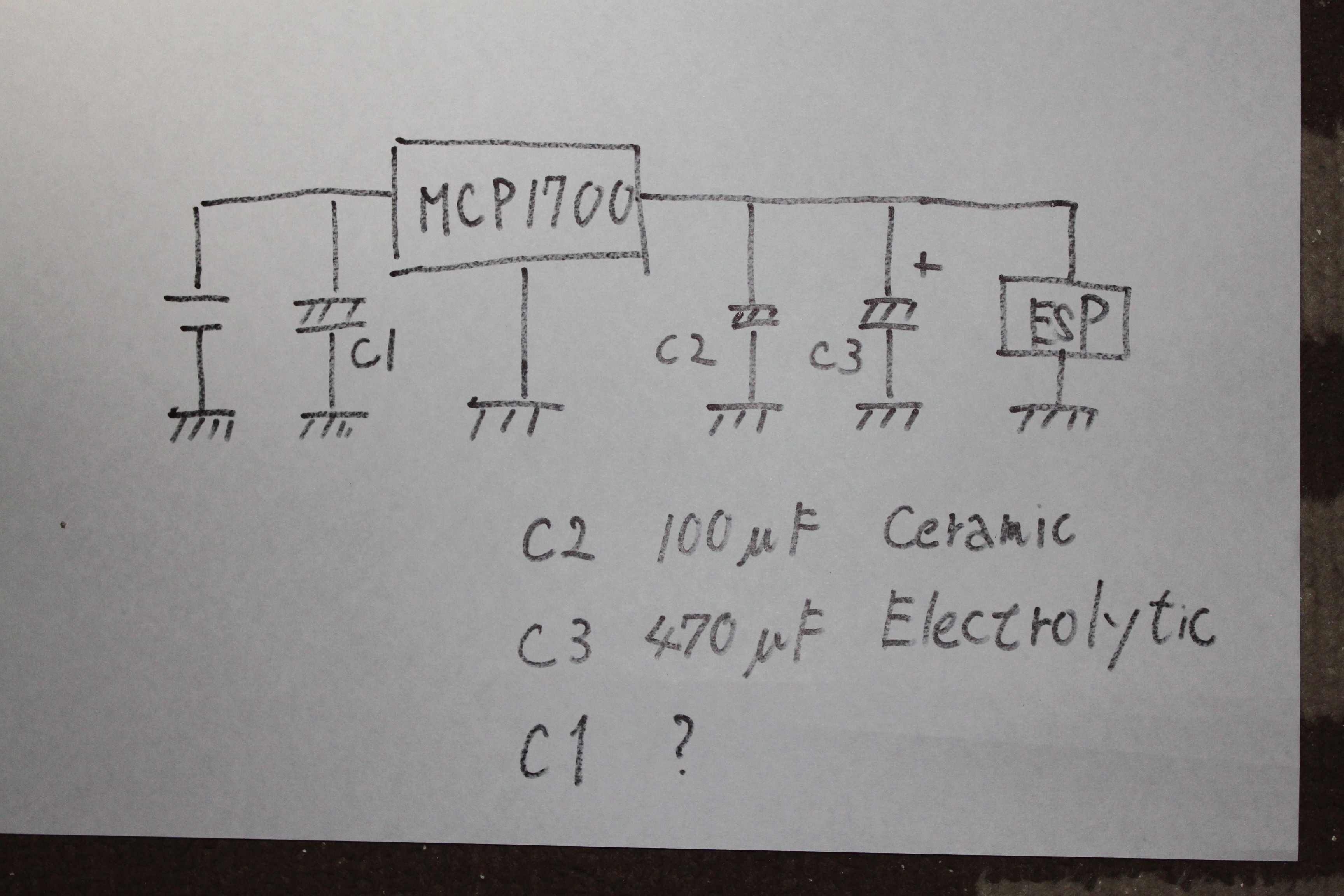
It as been a while but I am still experimenting. I now selected the MCP1700 as the LDO and so far it works well. It is specified for max 250mA and I see current peaking at over 400mA but only for very short periods. So far so good, I will let it run for a few months to see how it handles. The attraction here is that it has a low dropout and a very low Iq of 1.5uA. It is also in an easy to solder through-hole package.
@thakshak, what are you saying about these modules?
esp-12f looks like another revision of the esp-12 (last was esp-12e). It is supposed to use only 10uA in deep sleep. I will try it, but what I really want is an updated esp-07 with lower deep sleep current and more RAM. Rumour has it that these are planned for later this year.
esp-14 is a very different animal, I gather that it has a second processor on-board. See here.
Neither one is what I want but I now have a better idea of what works for me. On board I want:
suitable LDO (I use MCP1700)
reset button/pin
pins for programmer
program button/pin (not critical)
power connection
spare GND/3.3v pins for device connection. I use DS18B20 (one-wire)
some projects will benefit from a good clock, should it be on-board?
maybe some battery/solar-charging management?
Any NodeMCU kind of board is good for the development phase, but for the commissioned boards I will prefer to have as little as is actually needed. I also will prefer stable connections so instead of pins I use screw blocks.
When a board is finally produced we should design a 3d-printable case to hold the board and a battery (or three).
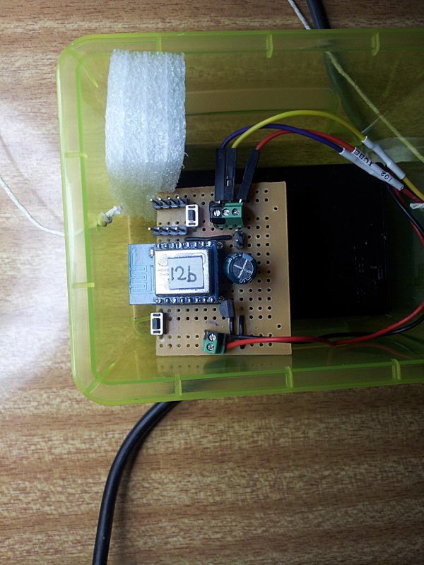
Here is a prototype I use, this board has a few buses on the back
The first thing to note is that the cap should have a low ESR in order to respond quickly, and I have it on the 3.3v side.
Examining the supply voltage (3.3v) should show (on a DSO) if it sags too much when current peaks arrive. As I recall, the early modules regularly consumed around 400mA for short periods (a few ms) which would stress the MCP1700 if there is no good cap. Later ones (12D/F) use less (some internal tuning or adjusted parameters?) and usually do not exceed the 250mA limit. I would also look at the wake-up signal to ensure it is strong enough as I remember cases where the failure mode was no wake-up.
I use 470uF electrolytic, but also used a 100uF Ceramic SMD.
And also important is the build quality. Circuits on breadboards work, for a while, but the ones I soldered (as in the earlier picture) perform rather well: an average run is 3 months (or longer, until the 3*AA NiMH batteries drain) with a 1m cycle, so about 130,000 cycles.
I am getting exactly same errors from my esp12f modules. I tried too many firmwares but did’nt change anything. Do you have any suggestion to solve it?
Hi Guys, After Reading all of the replies , i tried to apply them in my case but didn’t get the results.
I hope i will get it here.
Well the problem i am facing is
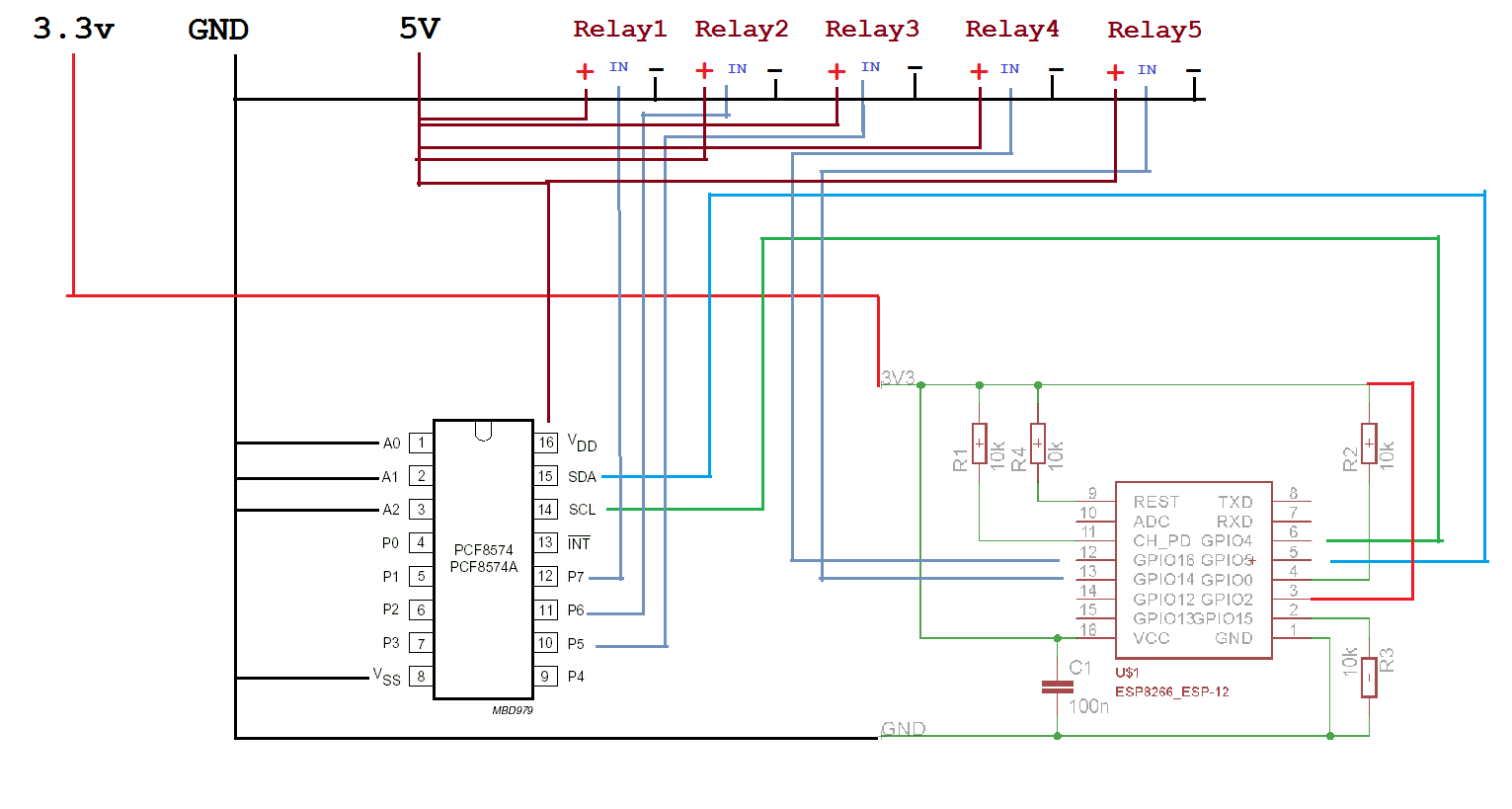
I am using ESP8266-12E with the rough circuit diagram shown here.
the esp8266-12e does not start in first attempt, I have to reset the module (or power on/off) multiple times and then it starts after number of attempts. The voltage reading in multi-meter shows appropriate all the times, even the voltage in ESP8266-12e module shows perfect. but the module does not start.
The Power 3.3 v is through AMS1117 3.3 V regulator.
Depending on your power source (the input to the AMS1117), it may help to have a large (440uF?) cap across the ESP power (probably where your C1 is). This will help if there is a very short voltage drop at boot time.
I notice that the i2c extender runs off 5v so you need to take care with SDA/SCL or run the extender at 3.3v.
Some relays (4/5) are driven directly from the esp (at 3.3v) and the others (1/2/3) from the extender (at 5v). Is this necessary?
In short, I do not think the issue is the ESP but rather the other parts disturbing the power.